The Main Panel
Go to the previous, next section.
This chapter describes how you interact with Geomview through the mouse and keyboard.
The usual way to start Geomview is to type geomview RET in a shell window (RET means hit the "Enter" key). It may take Geomview a few seconds to start up; one or more windows will appear and you can begin interacting with Geomview immediately.
It is also possible to specify actions for Geomview to perform at startup time by giving arguments in the shell command line. See section Command Line Options.
Here are the command line options that Geomview allows:
-c "(ui-panel main off)"Since command includes parentheses, which have special meaning to the shell, command must be quoted. Multiple -c options are allowed.
geomstuff or togeomview. This actually listens to the
named pipe `/tmp/geomview/objectname'; you can achieve the same
effect with the shell commands:
mkdir /tmp/geomview
mknod /tmp/geomview/objectname p
(assuming the directory and named pipe don't already exist), then executing the gcl command:
(geometry objectname < /tmp/geomview/objectname)
ui-panel command.
emodule-define command.
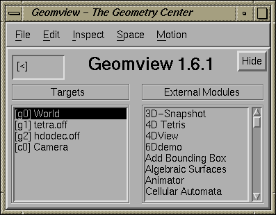
Normally when you invoke Geomview, three windows appear: the Main panel, the Tools panel, and one camera window. Geomview has many other windows but most things can be done with these three and so by default the others do not appear. This section of the manual introduces some basic concepts that are used throughout the rest of the manual and describes the Main panel.

The Main Panel
Geomview can display an arbitrary number of objects simultaneously. The
Targets browser in the Main panel displays a list of all
the objects that Geomview currently knows about. This browser has a
line for each object that you have loaded, plus some lines for other
objects. One of the other objects is called World and corresponds to
the all the currently loaded objects, treated as if they were one
object. Most of the operations that you can do to one object, such as
applying a motion or changing a color, can also be done to the "World"
object.
The Targets browser also has an entry for each camera. By default there is only one camera; it is possible to add more of them via the New Camera entry of the Main panel's File menu. Geomview treats cameras in much the same way as it does geometric objects. For example, you can move cameras around and add them and delete them just as with geometric objects. Cameras do not usually show up in the display as an object that you see. Each camera has a separate camera window which displays the view as seen by that camera. (It is possible for each camera to display a geometric representation of other cameras. See section Cameras.)
Because Geomview treats cameras and geometric objects very similarly, the term object in this documentation is used to refer to either one. When we need to distinguish between the two kinds of objects, we use the term geom to denote a geometric object and the word camera to denote a camera.
The object which is selected (highlighted) in the Targets browser is called the target object. This is the object that receives any actions that you do with the mouse or keyboard. You can change the target object by selecting a different line in the Targets browser. Another way to change the target object is to put the mouse cursor directly over a geom in a camera window and rapidly double-click the right mouse button. This process is called picking; the picked object becomes the new target.
Geomview objects are all known by two names, both of which are shown in the Targets browser. The first name given there, which appears in square brackets ([ ]), is a short name assigned by Geomview when you load the object. It consists of the letter `g' for geoms and `c' for cameras, followed by a number. The second name is a longer more descriptive name; by default this is the name of the file that the object was loaded from. The two names are equivalent as far as Geomview is concerned; at any point where you need to specify a name you can give either one.
To manipulate an object, make sure you that the object you want to move is the target object, and put the mouse cursor in a camera window. Motions are applied by holding down either the left or middle mouse button and moving the mouse. There are several different motion "modes", each for applying a different kind of motion. The MOTION MODE browser in the Main panel indicates the current motion mode. The default is "Rotate". You can change the current motion mode by selecting a new one in the MOTION MODE browser, or by using the Tools panel. For more information about motion modes, See section Using the Mouse to Manipulate Objects.
The Modules browser lists Geomview external modules. An external module is a separate program that interacts with Geomview to extend its functionality. For information on external modules, See section External Modules.
The menu bar at the top of the main panel offers menus for common operations.
To create new windows, load new objects, save objects or other information, or quit from geomview, see the File menu.
To copy or delete objects, see the Edit menu.
You can invoke any panel from the Inspect menu.
The Space menu lets you choose whether geomview operates in Euclidean, Hyperbolic, or Spherical mode. Euclidean mode is selected by default. For details about using Hyperbolic and Spherical spaces, See section Non-Euclidean Geometry.
Most actions that you can do through Geomview's panels have equivalent keyboard shortcuts so that you can do the same action by typing a sequence of keys on the keyboard. This is useful for advanced users who are familiar with Geomview's capabilities and want to work quickly without having to have lots of panels cluttering up the screen. Keyboard shortcuts are usually indicated in square brackets ([ ]) near the corresponding item in a panel. For example, the keyboard shortcut for Rotate mode is 'r'; this is indicated by "[r]" appearing before the word "Rotate" in the MOTION MODE browser. To use this keyboard shortcut, just hit the r key while the mouse cursor is in any Geomview window. Do not hit the RET key afterwards.
Some keyboard shortcuts consist of more than one key. In these cases just type the keys one after the other, with no RET afterwards. Keyboard shortcuts are case sensitive.
Many keyboard shortcuts can be preceded by a numeric parameter.
For example, typing ae toggles the state of drawing edges,
while 1ae always enables edge drawing.
The keyboard field in the upper left corner of the Main panel echos the current state of keyboard shortcuts.
For a list of all keyboard shortcuts, press the ? key.
There are several ways to load an object into Geomview.
The Files Panel
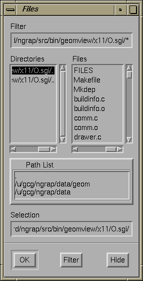
To select a file, double-click on its name in the browser at upper right, or click on its name and press the Return key, or type the file's name into the text box at the bottom of the browser and press Return.
If the selected file contains OOGL geometric data, it will be added to the geomview Targets browser. If it contains GCL commands instead, the file will be interpreted. See section gcl: the Geomview Command Language.
When the Files panel first appears, the directory selected in the directory browser is the current directory -- the one from which you invoked Geomview. The file browser shows all the files in this directory, including ones that are not Geomview files. If you try to load a file that doesn't contain either an OOGL object or Geomview commands, Geomview will print out an error message.
The directory browser also lists a second and third directory in addition to the current directory. The second one, which ends in `data/geom', is the Geomview example data directory. This contains a wide variety of sample objects. It also contains several subdirectories. In particular, the `hyperbolic' and `spherical' subdirectories have sample hyperbolic and spherical objects, respectively. Directory entries in the browser look just like file entries; to view a subdirectory, click on it.
The third directory shown in the directory browser, which ends in `geom', contains several subdirectories with other Geomview files in them. These are used less frequently than the ones in the `data/geom' directory.
You can change the list of directories shown the Files
panel's directory browser by using the set-load-path command;
see section gcl: the Geomview Command Language.

The Load Panel
load, geometry, new-geometry, and read
gcl commands allow you to load an object into Geomview;
See section gcl: the Geomview Command Language.
Geomview lets you manipulate objects with the mouse. There are six different mouse motion modes: Rotate, Translate, Cam Fly, Cam Zoom, Geom Scale, and Cam Orbit. The tools panel has a button for each of these modes; to switch modes, click on the corresponding button. You can also select these through the Motion Mode browser on the Main panel.
This section describes basic mouse interaction. For details, see section The Commands Panel.

The Tools Panel
Each of the motion modes uses a common paradigm for how the motion is applied. In particular, each depends on the current target object and the current center object. These are explained in the following paragraphs.
The current target object is shown in the Target field in the Tools panel. This is the same as the selected object in the Targets browser in the Main panel, and you can change it by either selecting a new object in the browser, by typing a new entry in the field, or by picking an object in a camera window by double-clicking the right mouse button with the cursor over the object.
The current center object is shown in the Center field in the Tools panel. Its default value is the special word "target", which means that the center object is whatever the target object is. You can change the center to any object by typing it in the Center field. The origin of the center object is held fixed in Rotate and Orbit modes. Normally the center object is one of the existing geoms listed in the Targets browser, and the actual center of rotations is the origin of that object's coordinate system. It is possible, however, to select an arbitrary point of interest on an object as the center. For details, see section Selecting a Point of Interest.
You apply a mouse motion by holding down either the left or middle mouse button with the cursor in a camera window and moving the mouse. Most of the modes have inertia, which means that if you let go of the button while moving the mouse, the motion will continue. It may be helpful to imagine the mouse cursor as being a gripper; when you hold a mouse button down, it grips the target object and you can move it. When you let go of the mouse button, the gripper releases the object. Letting go of the mouse button while moving the mouse is like throwing the object -- the object continues moving independent of the mouse. Inertia can be turned off; see the Main panel's Motion menu, described below.
Generally, the left mouse button controls motion in the screen plane, while the middle mouse controls motion along or around the forward direction.
Pressing the shift key while dragging with left or middle mouse buttons in most motion modes gives slow-speed motions, useful for fine adjustment.
You can pick any point on an object (not just its origin) as the center of motion by holding down the shift key while clicking the right mouse button; this chooses a point of interest.
The middle mouse button in Rotate mode rotates the target object about an axis perpendicular to the view plane.
In Euclidean space, the center object is essentially irrelevant for translations. In hyperbolic and spherical spaces, where translations have a unique axis, this axis is chosen to go through the origin of the center object.
Cam Fly affects the camera window that the mouse is in; it ignores the target object and the center object.
In general Cam Orbit does not move the target object, although if the current camera is selected as the target and the center is also the target, it will pivot that camera about itself just as in Cam Fly mode.
Scaling is meaningful only in Euclidean space; attempts to scale are ignored in other spaces.
Geom Scale mode does not have inertia.
The Stop, Look At, Center, and Reset buttons on the Tools panel perform actions related to motions but do not change the current motion mode.
The keyboard command h, which does not correspond to a panel button, stops the current motion for the target object only.
The Look At command is unreliable in non-Euclidean spaces.
The Tools panel also sports a Main button, to invoke the main panel in case it was dismissed or buried, and a Done button to close the Tools panel.
The Main panel's Motion Style menu has special controls affecting how mouse motions are interpreted.
It is sometimes useful to specify a particular point on some object in a geomview window as the center point for mouse motions. You can do this by shift-clicking the right mouse button (i.e. click it once while holding down the shift key on the keyboard) with the cursor over the desired point. This point then becomes the point of interest. The point of interest must be on an existing object.
Selecting a point of interest simplifies examining a small portion of a larger object. Shift-right-click on an interesting point, and select Orbit mode. Use the middle mouse button to approach, and the left mouse to orbit the point, examining the region from different directions.
When you have selected a point of interest, the current center object changes to an object named "CENTER", which is an invisible object located at the point of interest. In addition, mouse motions for the window in which you made the selection are adjusted so that the point of interest follows the mouse.
You can change the point of interest at any time by selecting a new one by shift-clicking the right mouse button again. You can cancel the point of interest altogether by shift-clicking the right mouse button with the cursor on the background (i.e. not on any object). This changes the center object back to its default value, "target".
The object named "CENTER", which serves as the center object for the
point of interest, is a special kind of geom called an "alien". It does
not appear in the Targets browser. By default it has no
geometry associated with it and hence is invisible. You can, however,
explicitly give it some geometry using a GCL command, causing it to
appear. Use the geometry command for this: (geometry
CENTER geometry), where geometry is any valid geometry.
For example, (geometry CENTER { < xyz.vect }) causes the file
`xyz.vect', which is one of the standard example files distributed
with geomview, to be used at the geometry for CENTER.
What happens internally when you select a point of interest is that the center is set to the object called CENTER, and that object is positioned at the point of interest. In addition, in order for mouse motions to track the point of interest, the current camera's focal length is set to be the distance from the camera to the point of interest. You can accomplish this via GCL with the following commands:
(if (real-id CENTER) nil (new-alien CENTER {}))
(ui-center CENTER)
(transform-set CENTER universe universe translate x y z)
(merge camera cam-id { focus d })
where (x,y,z) are the (universe) coordinates of
the point of interest, and d is the distance from that point to
the current camera, cam-id. The first command above creates the
"alien" CENTER if it does not yet exist.
Geomview uses a hierarchy of appearances to control the way things look. An appearance is a specification of information about how something should be drawn. This can include many things such things as color, lighting, material properties, and more. Appearances work in a hierarchal manner: if a certain appearance property, for example face color, is not specified in a particular object's appearance, that object is drawn using that property from the parent appearance. If both the parent and the child appearance specify a property, the child's setting takes precedence unless the parent appearance is set to override.
Every geom in Geomview has an appearance associated with it. There is also an appearance associated with the "World" geom, which serves as the parent of each individual geom's appearance. Finally, there is a global "base" appearance, which is the parent of the World appearance.
The base appearance specifies reasonable values for all appearance information, and by default none of the other appearances specify anything, which means they inherit their values from the base appearance. This means that by default all objects are drawn using the base appearance.
If you change a certain appearance property for a geom, that property is used in drawing that geom. The parent appearance is used for any properties that you do not explicitly set.
Geomview has three panels which let you modify appearances.
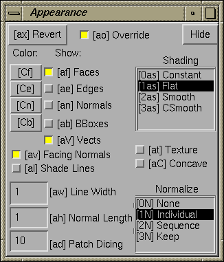
The Appearance panel lets you change most common appearance properties of the target object.
The Appearance Panel
The five buttons near the upper right corner under the word Draw control what parts of the target geom are drawn.
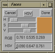
The four buttons under Color labeled Faces, Edges, Normals, and BBox let you specify the color of the corresponding aspect of the target geom. Clicking on one of them brings up a color chooser panel.
Color Chooser Panel
In the HSV color system, hue H runs from red at 0, green at .333, blue at .667, and back to red at 1.0. Saturation gives the fraction of white mixed into the color, from 0 for pure gray to 1 for pure color. Value gives the brightness, from 0 for black to 1 for full brightness.
Pressing the RGB or HSV button at top center switches the sliders to the other color system. You can adjust colors either via the sliders, or by typing in either the RGB or HSV text boxes.
Click OK to accept the color that you have chosen, or Cancel to retain the previous color setting.
The SHADING browser lets you specify the shading model that Geomview uses to paint the target geom.
The Facing Normals button on the Appearance panel indicates whether or not Geomview should arrange that normal vectors always face the viewer. If a normal vector points away from the viewer the color of the corresponding face or vertex usually is darker than is desired. Geomview can avoid this by using the opposite normal in shading calculations. This is the default. Using Facing Normals can give strange flickering dark or light shading effects, though, near the horizon of a fairly smooth facetted object. Press this button to use the normals given with the object.
The three text fields in the lower left corner of the Appearance panel are:
The Revert button on the Appearance panel undoes all settings in the target appearance. This causes the target geom to inherit all its appearance properties from its parent.
The Appearance panel's Override button determines whether appearance controls should override settings in the objects themselves -- for example, setting the face color will affect all faces of objects with multi-colored facets. Otherwise, appearance controls only provide settings which the objects themselves do not specify. By default, Override is enabled. This button applies to all objects, and to all appearance-related panels.
The Materials panel controls material properties of surfaces. It works with the target object in the same way that the Appearance panel does.
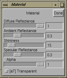
The Materials Panel
This button determines whether transparency is enabled. Geomview itself does not fully support transparency yet and on some machines it does not work at all. More specifically, the X, NextStep, and some SGI platforms ignore alpha information entirely, while other SGI platforms use the alpha information but the picture is guaranteed to be incorrect. Use RenderMan if you want real transparency: when transparency is enabled, a RenderMan snapshot will contain the alpha information.
The Lighting panel controls the number, position, and color of the light sources used in shading.
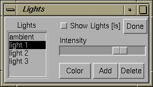
The Lighting Panel
The Lighting panel is different from the Appearance and Material panels in that it always works with the base appearance. This is because it usually makes sense to use the same set of lights for drawing all objects in your scene.
Geomview's Appearance, Materials, and Lighting
panels are constructed to allow you to easily do most of the appearance
related things that you might want to do. The appearance hierarchy that
Geomview supports internally, however, is very complex and there are
certain operations that you cannot do with the panels. The Geomview
command language (gcl) provides complete support for appearance operations.
In particular, the merge-baseap command can be used to change the
base appearance (which, except for lighting, cannot be changed by
Geomview's panels). The merge-ap command can be used to change
an individual geom's appearance. Appearances can also be specified in
OOGL files; for details, see section Appearances.
A camera in Geomview is the object that corresponds to a camera window. By default there is only one camera, but it is possible to have as many as you want. You can control certain aspects of the way the world is drawn in each camera window via the Cameras panel.
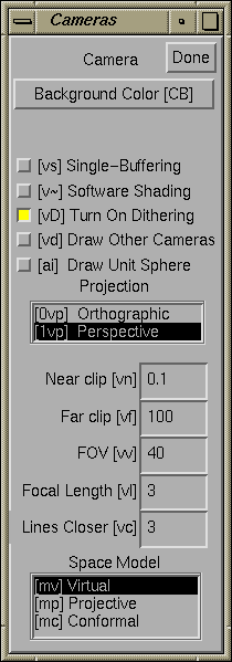
The Cameras Panel
To create new camera windows, use the v+ keyboard shortcut, or see the File menu on the Main panel.
Geomview's Save panel lets you store Geomview objects and other information in files that you can read back into Geomview or other programs.
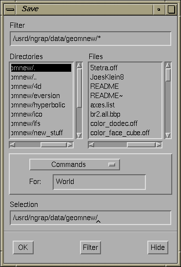
The Save Panel
If you specify `-' as the file name, Geomview will write the file to standard output, i.e. in the shell window from which you invoked Geomview.
The possible formats are given below. The kind of object that can be written with each format is given in parentheses.
PPM screen snapshots are only available with GL and Open GL, not plain X graphics. The window should be entirely on the screen. Geomview will ensure that no other windows cover it while the snapshot is taken.
The Commands panel lets you type in a gcl command. When you hit RET, Geomview interprets the command and prints any resulting output or error messages on standard output. You can edit the text and hit RET as many times as you like, in general, whenever you hit RET with the cursor in the Commands panel, Geomview tries to interpret whatever text you have typed in the text field as a command.
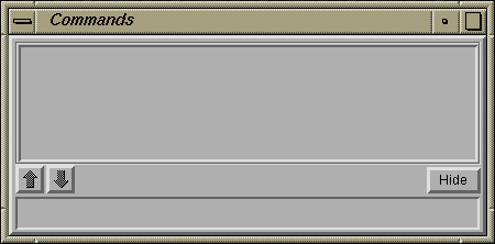
The Commands Panel
[Move this.] Normalization is a kind of scaling; Geomview can scale an object so that it fits within a certain region. The main point of normalization is to allow you to easily view all of an object without having to worry about how big it is. We are gradually replacing Geomview's normalization feature with more robust camera positioning features. In general, the best way to make sure you are seeing all of an object is to use the Look At button on the Tools panel. Normalization may be completely replaced by this and other features in a future version of Geomview.
Normalization is a property that applies to each geom separately. The NORMALIZE GEOMETRY browser affects the normalization property of target geom. If the target geom is "World", it affects all geoms.
Most actions that you can do through Geomview's panels have equivalent keyboard shortcuts so that you can do the same action by typing a sequence of keys on the keyboard. This is useful for advanced users who are familiar with Geomview's capabilities and want to work quickly without having to have lots of panels cluttering up the screen. Keyboard shortcuts usually are indicated in square brackets ([ ]) near the corresponding item in a panel. For example, the keyboard shortcut for Rotate mode is 'r'; this is indicated by "[r]" appearing before the word "Rotate" in the MOTION MODE browser. To use this keyboard shortcut just hit the r key while the mouse cursor is in any Geomview window. You don't need to press the RET or SPACE keys.
Some keyboard shortcuts consist of more than one key. In these cases just type the keys one after the other, with no RET afterwards. Keyboard shortcuts are case sensitive. You can cancel a multi-key keyboard shortcut that you have started by typing any invalid key, for example the space bar.
Keyboard commands apply while the cursor is in any camera window and most control panels.
Many keyboard shortcuts allow numeric arguments which you type as a prefix to the command key(s). For example, the shortcut for Near clip in the camera panel is v n. To set the near clip plane to `0.5', type 0.5vn. Commands that don't take a numeric prefix toggle or reset the current value.
Most commands allow one of the following selection prefixes. If none is provided the command applies to the target object.
For example, g4af means toggle the face drawing of object g4.
Simply typing a selection prefix, like g4, doesn't yet select an object; that only happens when a command, like ae, follows the prefix. To select an object as the target without doing anything else to it, use the p command. So g3p selects object g3.
The text field in the upper left corner of the Main panel shows the state of the current keyboard shortcut.
In addition to the keyboard shortcuts for the panel commands, there is also a shortcut for picking a target object: type the short name of the object followed by p. For example, to select object g3, type g 3 p. This only works with the short names -- the ones that appear in square brackets ([ ]) in the Targets browser of the Main panel.
Below is a summary of all keyboard shortcuts.
Go to the previous, next section.