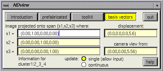
The basis vectors panel shows spanning vectors for the projective subspace used by the current window to view the currently selected object. In addition, it displays the camera displacement relative to the object, both as a displacement in the higher dimensional space, and as a displacement in the in the projective subspace (relative to the coordinates of the current window). The default mode is to update these values continually, but there is also an option to "update once", after which it will not continually poll Geomview and you can type in new values more easily.
To best understand what these numbers do, try changing them a little bit at a time. For example, replace the "camera view from" vector with a larger multiple. This should result in the camera moving away from the current object. (This is not the same as using zoom; see the toolkit help page for more details.)
Examples and explanation of changing the spanning vectors
Suppose you are looking at a standard projection from four dimensions into three, by chopping of the last coordinate. The spanning vectors may look like this (especially if you have just begun):
x-dir: (1.00, 0.00, 0.00, 0.00)
y-dir: (0.00, 1.00, 0.00, 0.00)
z-dir: (0.00, 0.00, 1.00, 0.00)
Suppose you type a change into the first vector so that it looks like (1.00, 1.00, 0.00, 0.00), and then (without moving the mouse) press return. The panel should update itself to look like this:
x-dir: (0.70, 0.70, 0.00, 0.00)
y-dir: (-0.70, 0.70, 0.00, 0.00)
z-dir: (0.00, 0.00, 1.00, 0.00)
The new set of vectors is again an orthonormal basis for the three dimensional projected subspace shown in the current window. Each time you type something in, the result is processed by a Gram-Schmidt algorithm, which normalizes the entry just typed in and adjusts all the other vectors to be orthonormal. "All the other vectors" means the other two displayed on the panel, as well as other basis vectors that complete a basis for the n-d space. In the above example, if you had modified the first vector to read (0.00, 0.00, 0.00, 1.00) instead of (1.00, 1.00, 0.00, 0.00), then nothing would have changed, because the Gram-Schmidt algorithm would have detected a singularity and returned the original values. The singular matrix in this case results from trying to set the first vector equal to a fourth (undisplayed) vector, and in general trying to type in a vector that is not linearly independent of the others will not effect any change. In order to avoid this difficulty, it is sometimes necessary to use a two step process. In this case, if the first vector is first changed to (.70,0.00,0.00,.70), and then to (0.00,0.00,0.00,1.00), it should give the intended result. You can change the "unseen" vectors by using this panel in combination with other cameras (of the same cluster) whose projected axes include those you wish to change.
This final paragraph is to be read by those who want to know about the internal implementation of this panel, in order to know _exactly_ what the modification of these values does. Casual users hopefully will not need to know the following details. The information given on this panel is basically four rows of a transformation matrix relating object coordinates to camera coordinates. This transformation matrix is actually the product of several other matrices maintained within Geomview. In order to allow several cameras to look at the same scene, Geomview keeps "camera to universe" matrices. In order to allow movement of different objects relative to one another, Geomview keeps "object to world" matrices. And in order to allow movement of the "world" all at once, Geomview keeps "world to universe" matrices. So to find an "object to camera" transform used in this panel, appropriate object, world, and camera matrices are multiplied together, and when the user modifies one of the values on the panel, the appropriate matrix is recalculated and sent back. Appropriate in this case means that, when the world is the current object (or targetgeom, in the language of Geomview) then modifications are made to the camera matrix, which may affect all the cameras attached to that camera's cluster. When something else is the current object (targetgeom), the object matrix is modified. In neither case is the world modified. ( It is possible to simulate a movement of the world either through repeated movements of cameras or objects, whichever is easier.) All of these matrices can be examined directly by using Geomview's command language. For example, to get the camera c0's matrix, give Geomview the command (echo (ND-xform c0))
 Go back to the beginning